REMOTE CONTROL TUTORIAL
This tutorial deals with using the Futaba controller with Tetrix robots.
(Credit: Mitchell Weeks - www.mitchellstech.weebly.om)
(Credit: Mitchell Weeks - www.mitchellstech.weebly.om)
STEP 1

Gather these materials:
-Controller
-Battery pack (8xAA battery or Tetrix rechargeable)
-Battery pack (2xAA battery)
-Tetrix switch
-RC motor controller circuit board
-Futaba controller
-Controller
-Battery pack (8xAA battery or Tetrix rechargeable)
-Battery pack (2xAA battery)
-Tetrix switch
-RC motor controller circuit board
-Futaba controller
STEP 2
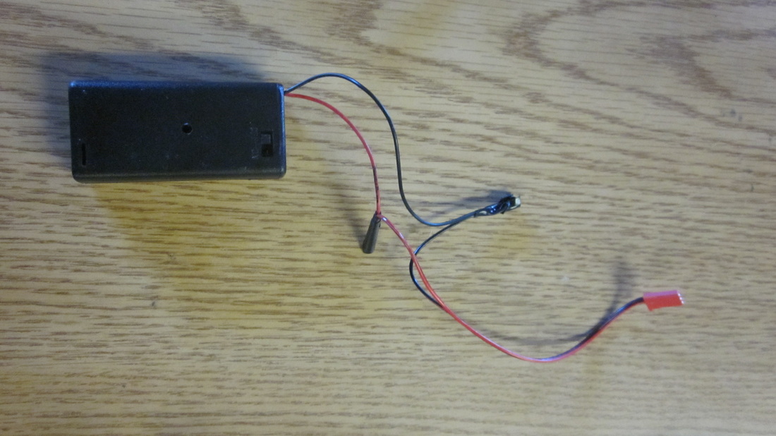
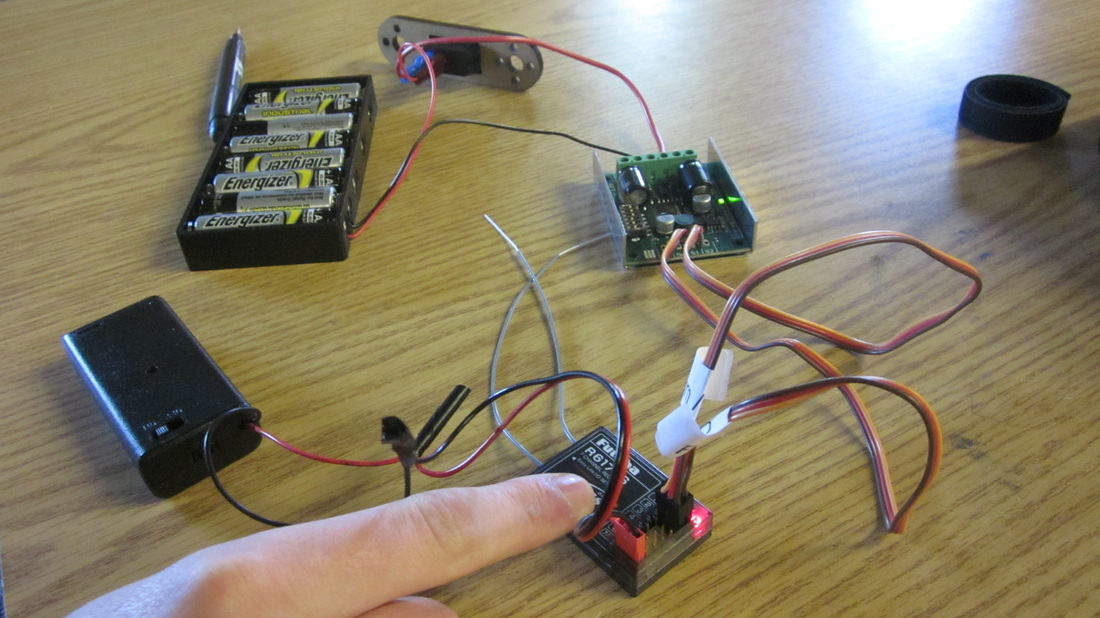
Ensure you have a double-AA battery pack with a servo connector spliced onto the end. If one is not available, obtain a three-pronged, two-contact servo wire and connect it to the battery pack contacts as shown.
STEP 3
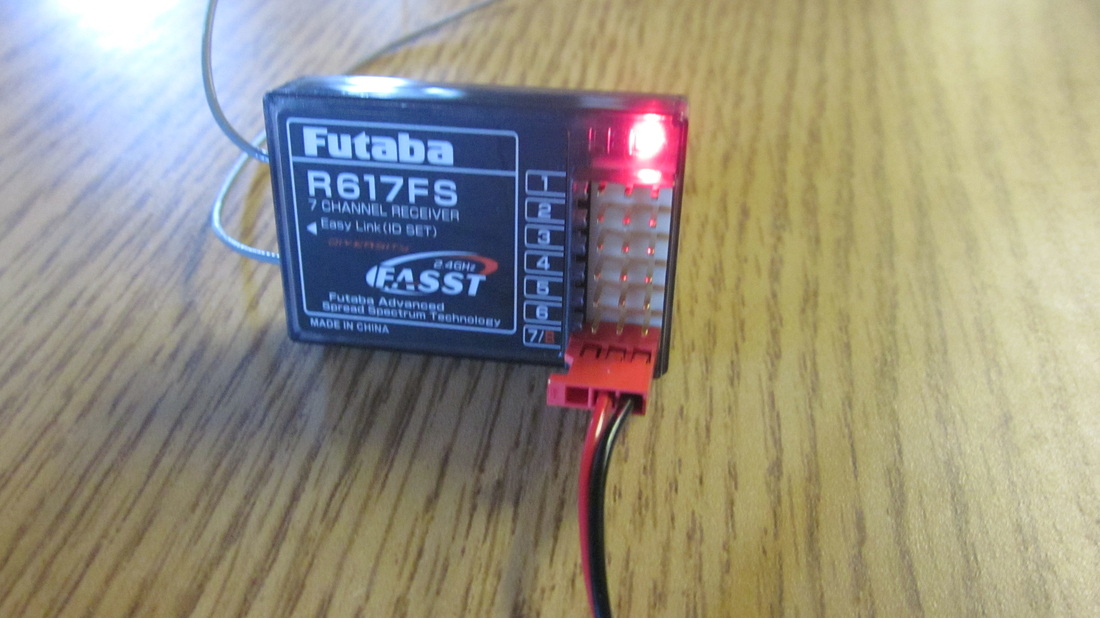
Connect the end of this servo connector into the receiver's "7/8" port. Turn the battery pack on and ensure that the receiver is powered.
STEP 4
8xAA Battery Pack:
If it is connected, disconnect the rechargeable battery cable from the Tetrix switch.
Tetrix Rechargeable Battery Pack:
Leave it connected and skip to step 6 using these parts.
If it is connected, disconnect the rechargeable battery cable from the Tetrix switch.
Tetrix Rechargeable Battery Pack:
Leave it connected and skip to step 6 using these parts.
STEP 5
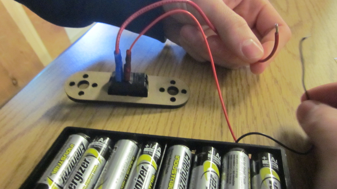
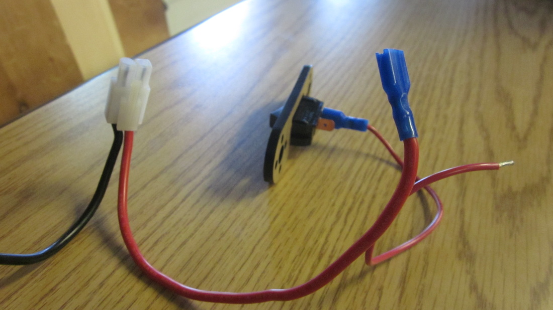
Connect the 8xAA battery pack's red connector to the switch. One red and one black wire should be free from the switch and battery pack, respectively.
STEP 6
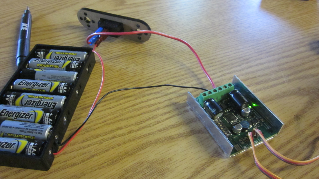
Connect the two free red and black contacts to the motor controller's B+ and B- wire inputs, respectively.
STEP 7
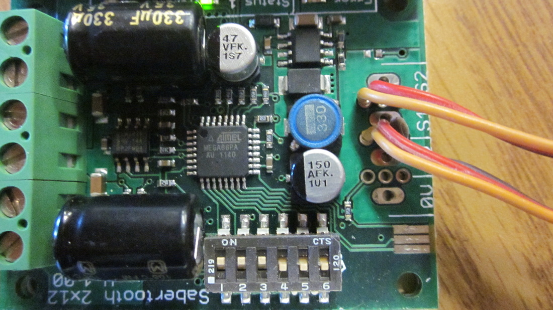
From left to right, the DIM swithes on the controller (pictured here as a row of switches near the bottom of the circuit board) should be configured as shown for normal (car) operation.
These switches change how the Futaba controller's joysticks move the motors. Experiment with them to obtain the motor directions and controls you desire.
These switches change how the Futaba controller's joysticks move the motors. Experiment with them to obtain the motor directions and controls you desire.
STEP 8
Connect the labeled switches from the motor controller to the receiver's channels one and two. These wires control the forward/back and turning capabilities of the motors connected.
STEP 9
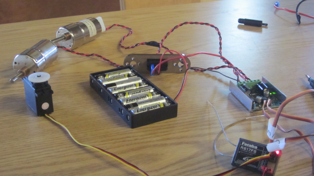
Connect up to two motors and three additional servos to the receiver. The entire assembly pictured here is mounted on the robot is controls.
The controller should already be configured with its receiver.
The controller should already be configured with its receiver.
